Take a Dumb Remote, and Give It An Education
The other day my wife came home from the local big box store with some light-blocking, motorized cell shades for our bedroom. I thought, this is great, no more annoying sun pouring in first thing in the morning and waking us up, and I mean come on…it would be one more fun gizmo to hook up to the oldest smart house ever. Well, my excitement was rather short lived. While reading the instructions it quickly became clear that while the box says that it integrates with home assistants like Google and Alexa, the apps and API were not yet ready from the manufacturer 😞
I grudgingly went ahead and installed the shades, and stewed in the fact that I would have to reach for the remote every time I wanted to raise or lower the shades.
Just as I thought I had made my peace with the new shades, I though to myself “even though there is no app, they are a very dumb remote”. They are just a set of simple momentary buttons to control various features. I sat there and clicked buttons over and over on one of the remotes that we were not using (we have 4, so there are some spares) over and over and over. I though, why can’t I make a modern version of one of those silly drinking birds? Well, it turns out that I could, so I did.
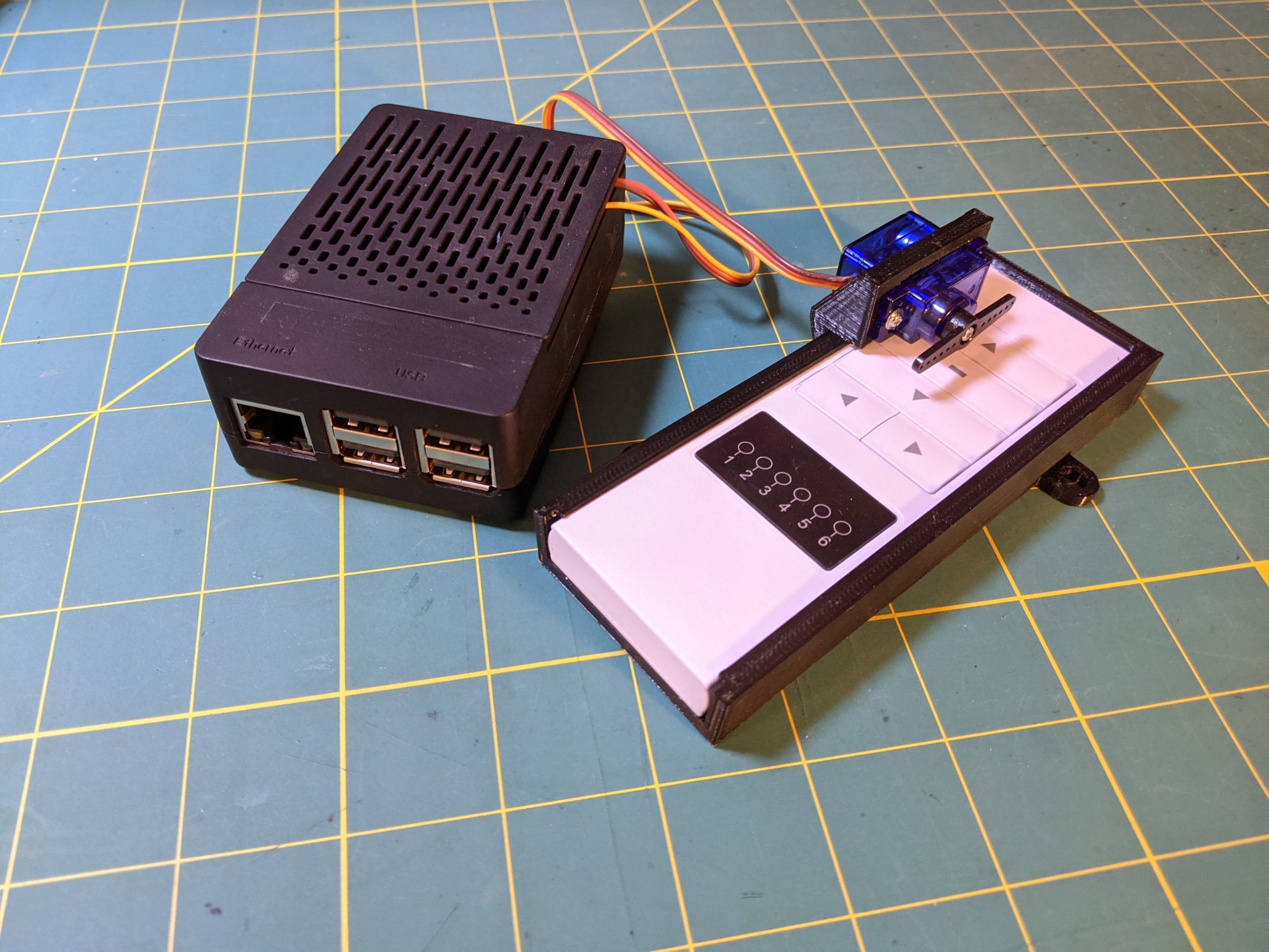
I figured I could use some sort of mechanical arm to press the buttons that I needed. I decided that I would use a micro servo (SG92R) that I had laying around with a straight double-arm, to rotate one way or the other and press the up or down buttons and then return to center. But I would need to some how non-destructively attach this servo to the remote in such a way as it would be secure to push. I fired up Sketchup, say what you want but it is my go to app for 3d modeling, and after some quick measurements with a caliper I had designed a cradle that the remote would slide into, and that would support the servo in the correct position, at least I thought it would.
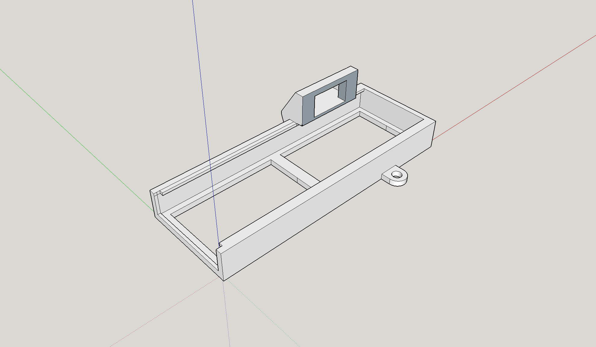
After waiting for the 3d print to run on my printer, and then waiting some more, I was rewarded with a newly created piece that never existed before.
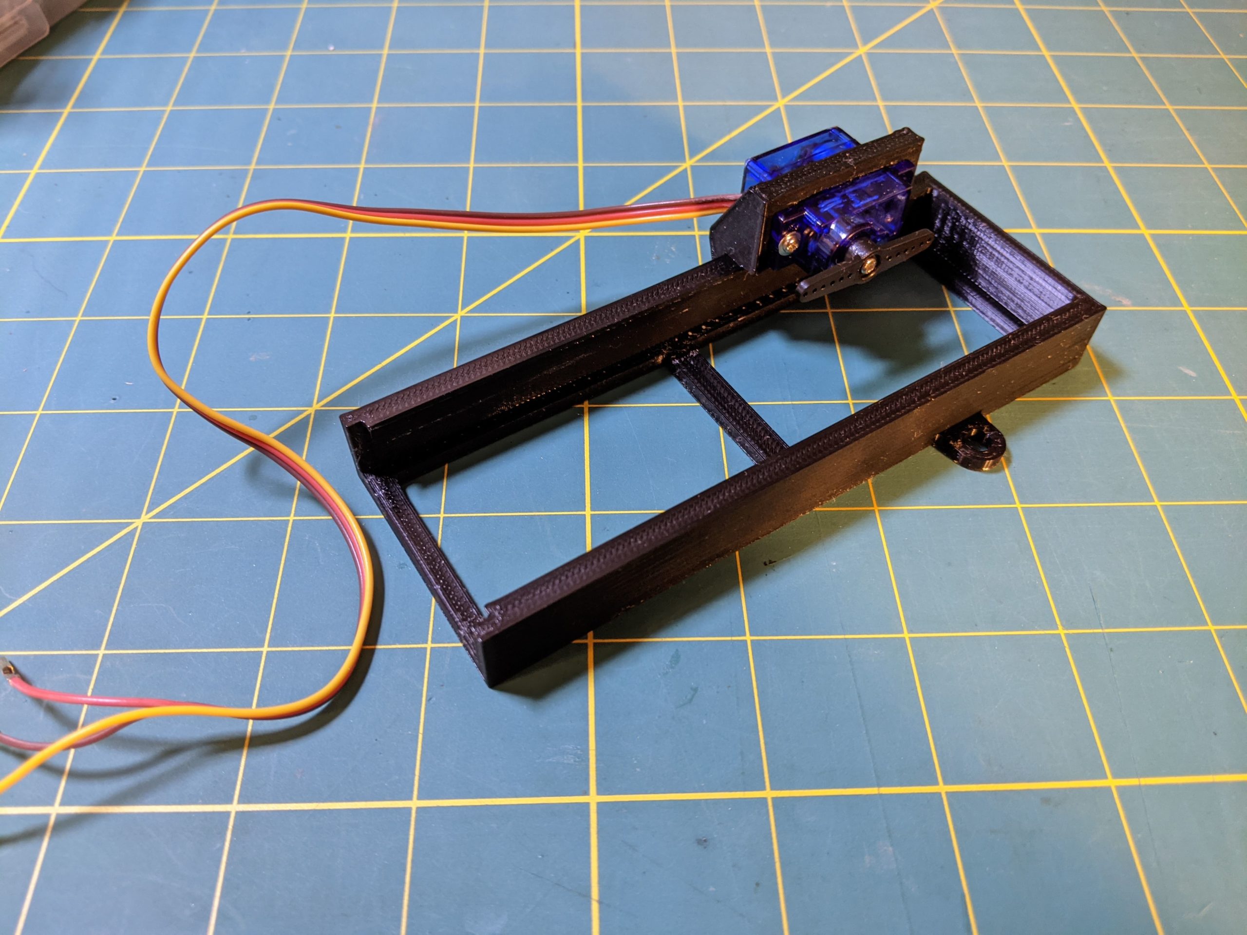
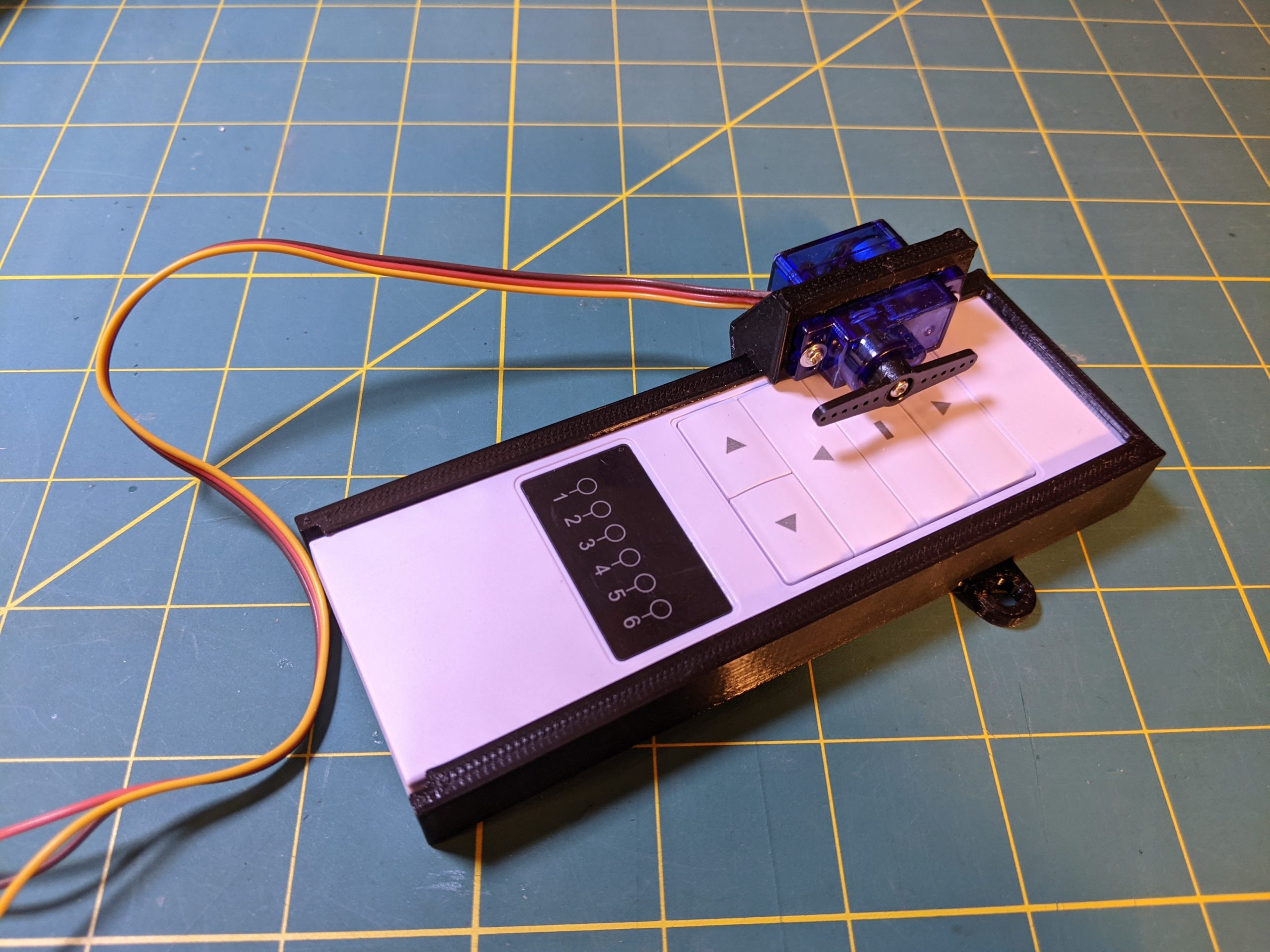
A quick test fit, and the remote fits! I had to do a little trimming to get the servo to fit as I forgot to take into account that the wires stick out on the side, but no big deal.
So now that the hard part? Easy part? is done, time to move on to make this thing now do something. I decided that I was going to use a Raspberry Pi for this project. Why you ask? Well, for starters I have never tried to build a hardware level project on a Pi. I have LOTS of experience building things on Arduino and other micro-computers, but not a Pi. I have built gaming consoles, music platforms, and even an OctoPrint controller for my 3d printers, but never anything like this. I also had an extra model 3 sitting around not doing anything, so beggars can’t be choosers.
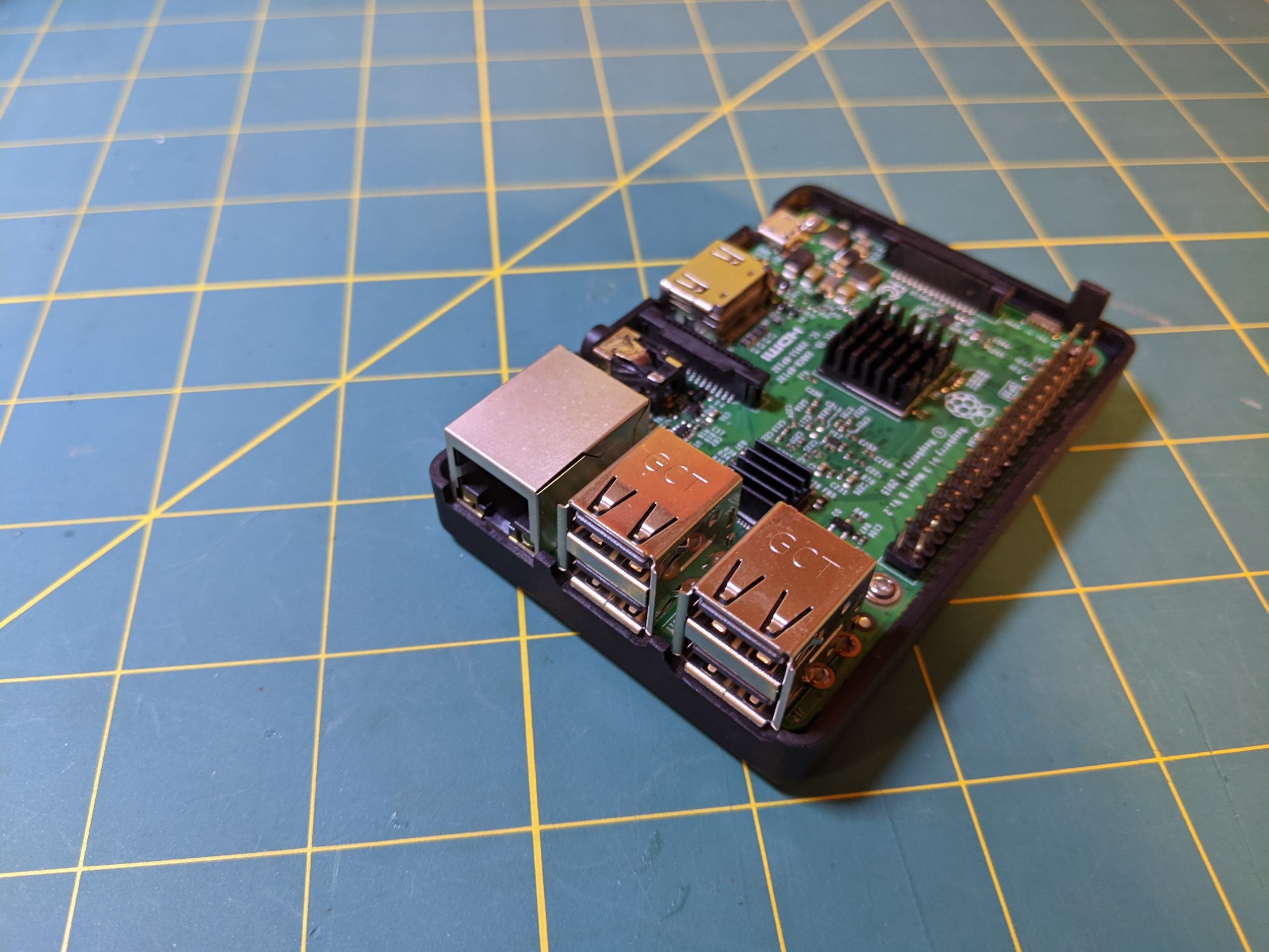
Now, I know that the pins on the Pi are roughly equivalent to those on an Arduino, and once I found a diagram of the pin-out, I was off to the races. I plugged the servo into the pins for 3.3 volts (pin 1), ground (pin 6), and picked random pin 11 for PWM controls, more about that later on.
I had to make a decision: how would I tell the Pi to control the servo? While there are lots of ways that this can be done, I decided that I would use Python as it was easy and quick to prototype and test the code. I cobbled together a quick script that would take in an argument from the script call on the command line. This argument would tell the script whether to “push the raise the shade” button or the “lower the shade button”. Really what it was doing was updating the duty cycle of the servo to rotate one way or the other. Here is what I would up with:
import RPi.GPIO as GPIO
import sys
from time import sleep

servoPin       = 11 #set the header pin that we will control the servo with
direction      = sys.argv[1] #read in the direction that the servo should move
sleepDur       = 0.4 #duration to sleep between commands
neutralPos     = 7.5 #the neutral position of the servo
upPos        = 5 #the left position of the servo
downPos       = 10 #the right position of the servo

GPIO.setmode(GPIO.BOARD)
GPIO.setup(servoPin,GPIO.OUT)
GPIO.setwarnings(False) #supress the annoying warnings

pwm = GPIO.PWM(servoPin,50) #set the servo pin to use 50hz
pwm.start(0)


# this function takesc in the angle to be set on the servo
# a = the angle to be set in the duty cycle
def setAngle(a):
    pwm.ChangeDutyCycle(a)
    sleep(sleepDur)
    pwm.ChangeDutyCycle(neutralPos)
    sleep(sleepDur)

if(direction == 'up'): #this will raise the shades
    setAngle(upPos)

if(direction == 'down'): #this will lower the shades
    setAngle(downPos)


pwm.stop()
GPIO.cleanup()
Pretty simple right? The only real trick with controlling a servo in this way, is that you need to know the PWM control values for your particular make and model as they CAN vary slightly. In my case, neutral is a value of 7.5, left is 5, and right is 10. With this information I was able to test and get the servo to move just far enough to push either button. You will also see that after I make the servo turn to push a button that I then reset it to neutral. I also leave a little time using SLEEP in between each command to account for the time needed to actually move the servo arm. In a pinch, you can also creatively use sleep to shorten the servo rotation by basically not leaving enough time to finish its movement. Putting it all together: remote in the cradle, servo attached, plugged into pi, and running script from command line and EUREKA! This is looking and working just like I had hoped it would.
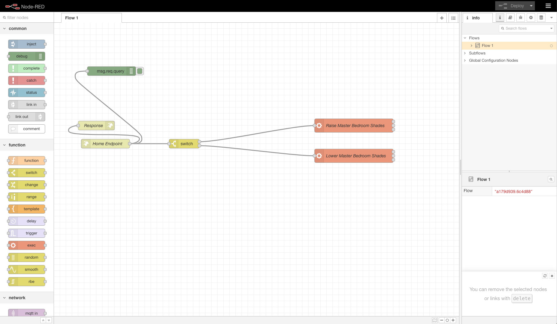
Now that I have the hardware together and script running, the next task is to somehow allow a request from Google Home, our assistant of choice, to trigger the servo to move. If you are not already familiar with it, you really need to look into Node-RED. Long story short, it is built on Node and allows for the creation of custom workflows to be created on Mac, PC, Raspberry Pi, etc. Install and configuration instructions will help you get it up and running, as well as secured. Once you have that completed, follow their instructions for accessing the dashboard and then you can create a simple Webhook end-point.
I created mine using the HTTP In and Exec nodes. The HTTP In creates the webhook end-point, and Exec runs the Python script that I created earlier. I added a switch node toward the end of my testing to allow me to determine what I was trying to do based on querystring values that I will pass in the URL.
I created a pattern that looks like: /home/io/i/?room=master&device=shade&action=[up/down]. I use this for other things around the house hence the more complicated querystring and pattern but you can simply as needed.
Here is my sample nodes layout:
To test, I simply entered the URL of my Pi on my local network and passed it the querystring parameters. Now, this doesn’t happen too often, but it fired the first time and the servo moved as it was supposed to. This means that I could trigger the shades to go or down from any computer on my home network, so of course I went around to different devices and tried it like the geek that I am. To be able to trigger these same commands from anywhere, I needed to port forward the IP of my Pi, and the port for Node-RED through my router to expose it. I am unfortunately still using the crappy router provided by Xfinity here at home. I have a nice new Netgear router ready to go, but I have had nothing but issues with trying to get it working on the Xfinity network…but that is a story for another time.
Now I was getting excited. I only had one more task that I needed to complete before I could continue to be remote free for all of our home automations. For the last piece of this puzzle, create custom trigger commands for Google Home, I went back to an oldie but a goodie, IFTTT. IFTTT, if you are not familiar with it already, stands for “If This Than That”. Basically it is a service that lets you create triggers and then perform actions. I created two new commands for my Google Home to listen to, and respond to. Using the IFTTT Webhooks I can make requests to the end-point that I created in Node-RED on the Pi. I created two IFTTT webhook triggers and gave the map appropriately named commands like “Lower the bedroom shades”, and had them pass the corresponding querystrings like: /home/io/i/?room=master&device=shade&action=down. I worked through all of the settings, and after a short wait for IFTTT to pass the new commands to Google (my account is linked already) I was ready to utter my first attempt.
Speaking slowly and clearly, I asked the house to lower the shades in our bedroom. Quicker than I thought it would happen, it started. I heard the servo whine and move. I heard the corresponding button click and then release, as the servo moved back to neutral. I heard the shade motors whir as they began to close the shades, that up till now, could only be controlled by manually pressing the remote buttons. SUCCESS!
Now what will I do next…hmmmm.